MOORING BUOYS
I - TYPOLOGY
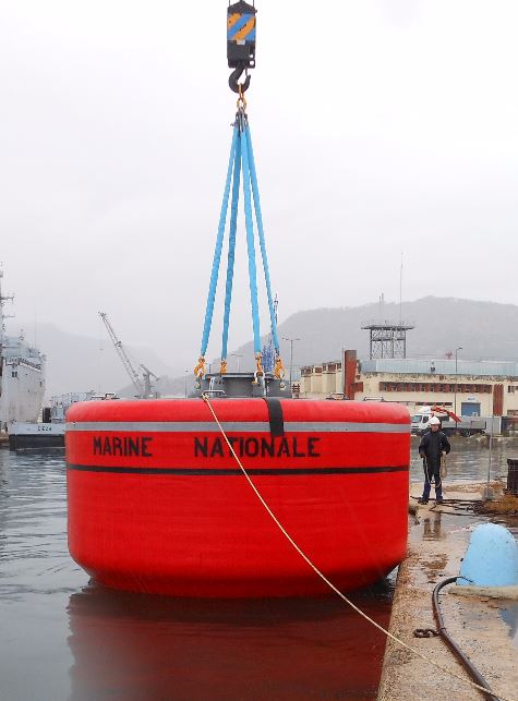
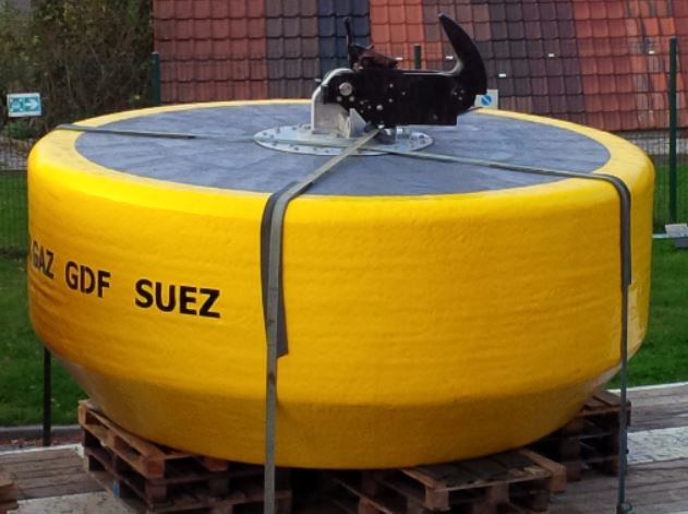
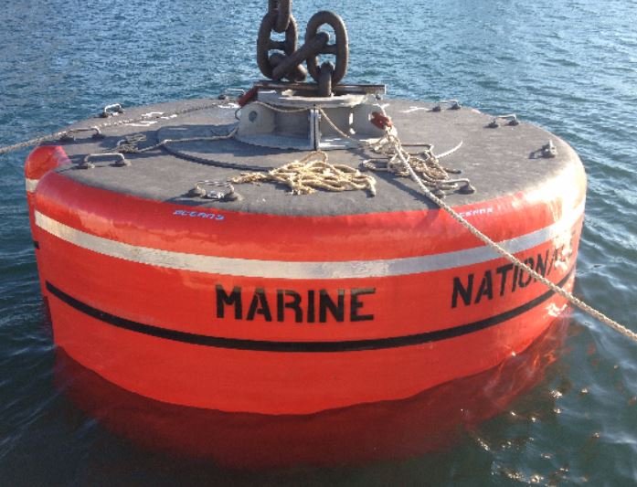
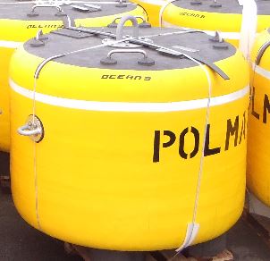
A) MOORING BUOY WITH STEEL FRAME
Those buoys are for the mooring of vessels with variable displacement, tonnage and length – Total buoyancy ranging from 3t to 40t, more if required for specific usage – Either with a fixed through steel arrangement to distribute the forces from the mooring line or removable elements or bespoke steel work. Various options, elements, fixings are available.
B) MOORING BUOY WITH REMOVABLE STEEL FRAME
Those buoys are for the mooring of vessels with variable displacement, tonnage and length – Total buoyancy ranging from 3t to 40t, more if required for specific usage – Either with a fixed through steel arrangement to distribute the forces from the mooring line or removable elements or bespoke steel work. Various options, elements, fixings are available.
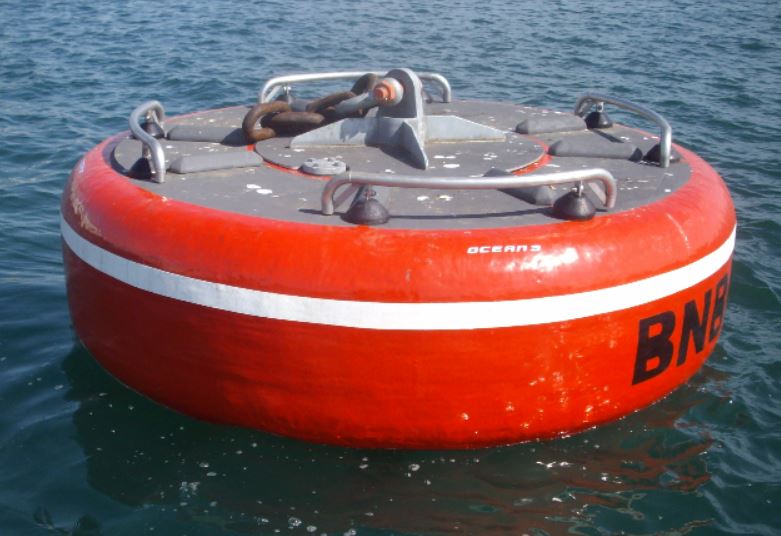
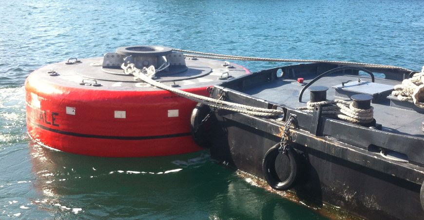
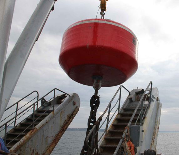
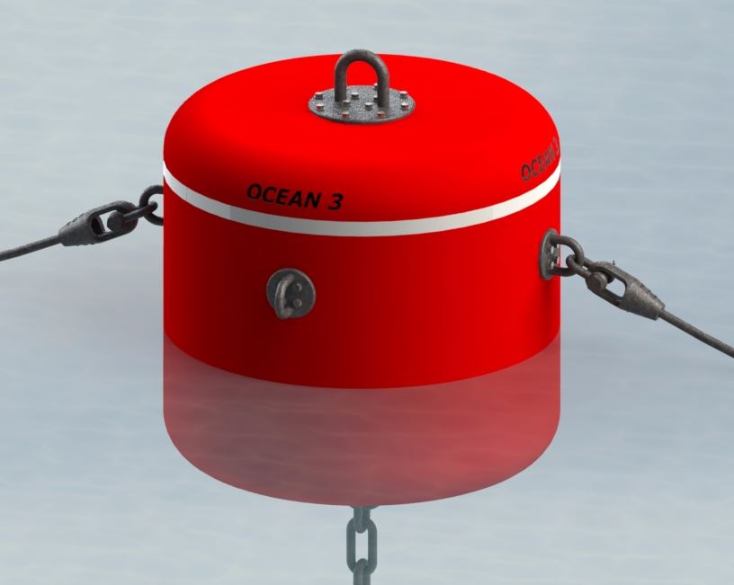
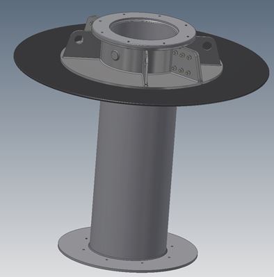
C) THROUGH MOORING BUOY
Those buoys are for the mooring of vessels with variable displacement, tonnage and length – Total buoyancy ranging from 3t to 40t, more if required for specific usage – Either with a fixed through steel arrangement to distribute the forces from the mooring line or removable elements or bespoke steel work. Various options, elements, fixings are available.
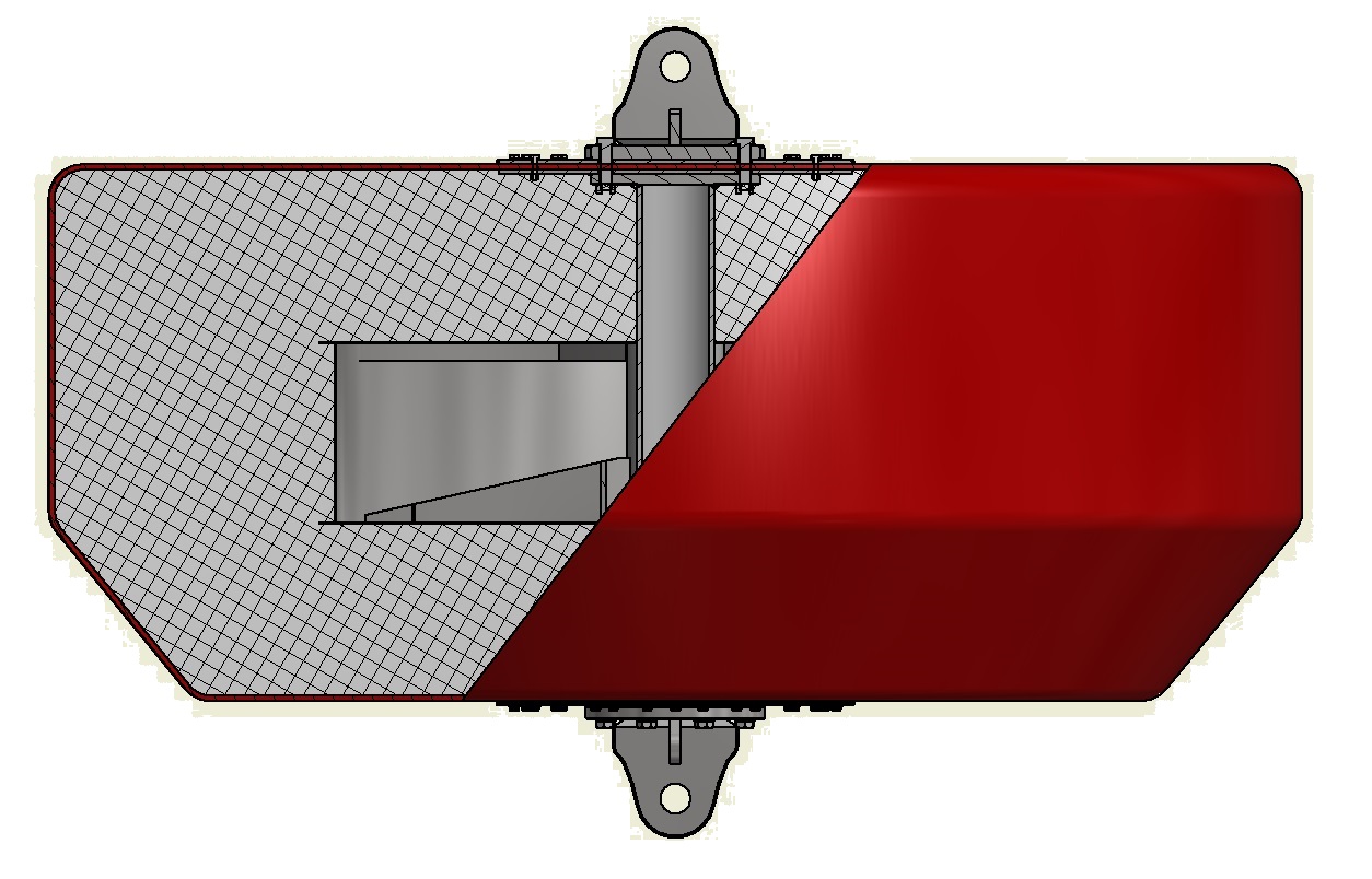
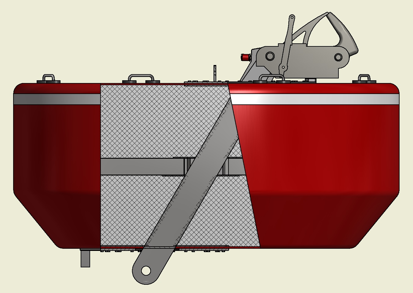
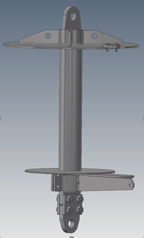
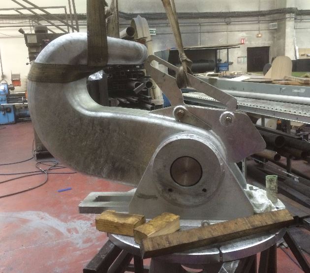
D) ANGLED STEEL FRAME MOORING BUOY
Those buoys are for the mooring of vessels with variable displacement, tonnage and length – Total buoyancy ranging from 3t to 40t, more if required for specific usage – Either with a fixed through steel arrangement to distribute the forces from the mooring line or removable elements or bespoke steel work. Various options, elements, fixings are available.
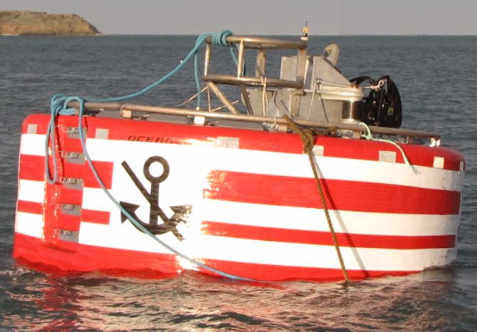
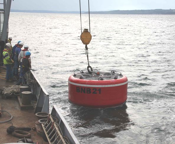
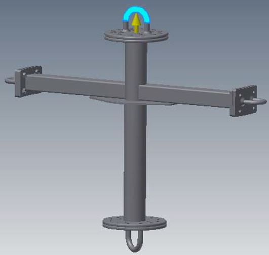
E) FLOATING BARRIER MOORING BUOY
Buoys of 0.7t to 2t of buoyancy, designed for the mooring of anti-intrusion or anti-pollution barriers. These buoys will have a horizontal frame so to attach the barriers on its side, also with the normal top and bottom mooring points. Various options, elements, fixings are available.
II - GENERAL DATA
A) SPECIFICATION
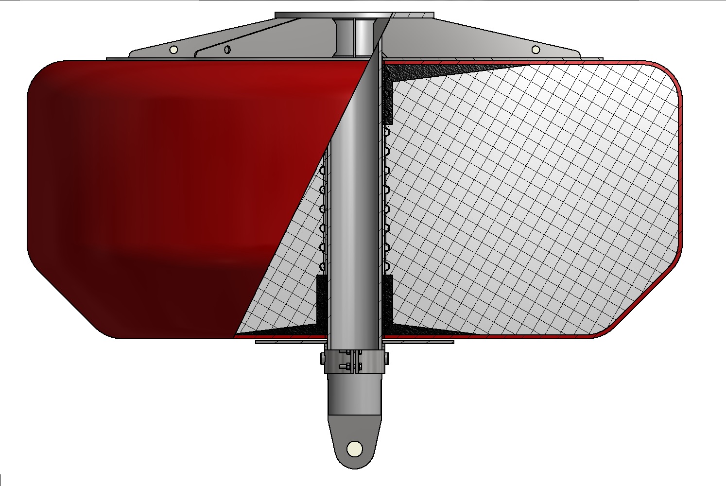
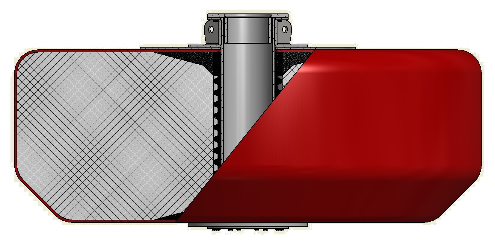
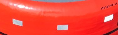
OCEAN 3 mooring buoys are typically made from a core of Polyethylene (PE) foam which will recover its shape after compression, 100% closed cell of various densities depending on usage. Such foam will guaranty no water absorption in case of damage. It allows a compression of up to 60% of its original volume for short periods of time, to regain its shape, meaning they allow for energy absorption, such as a fender.
The choice of the foam density relies on setting up the best parameters between weight and its ability to compress (as the higher the density the less the buoyancy will be).
A conical shape on the bottom part will allow it to be more stable in the water.
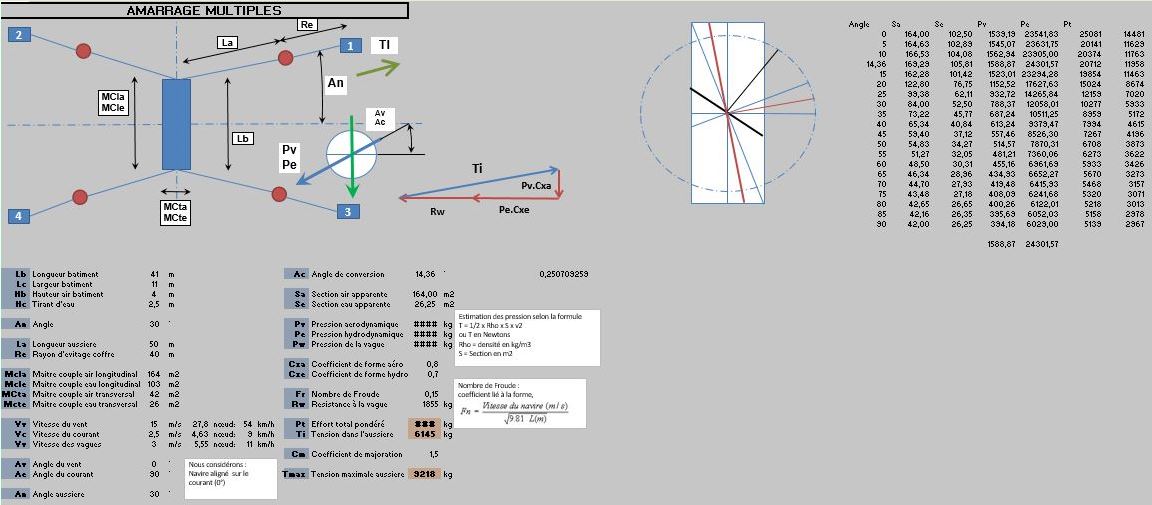
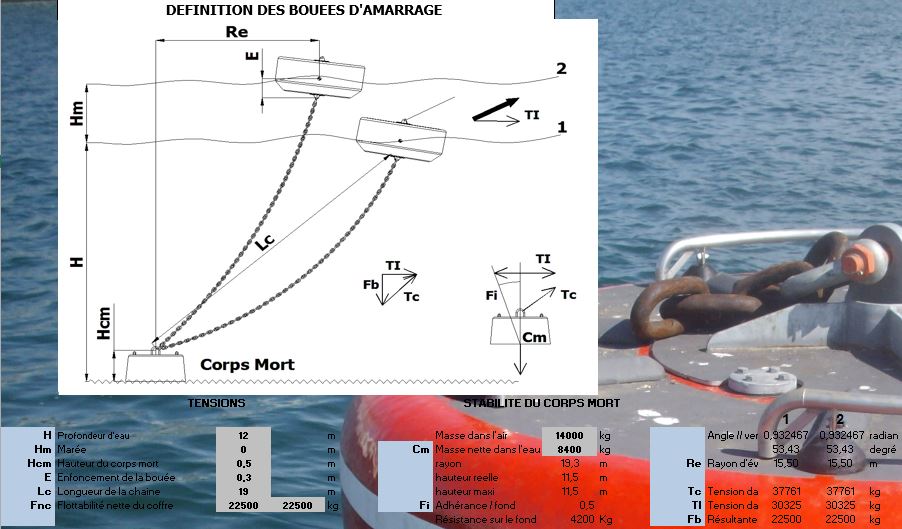
B) CALCULATION OF THE TENSION LINE MOORING FORCES
A calculation needs to be established as to working out the total force coming from the mooring line.
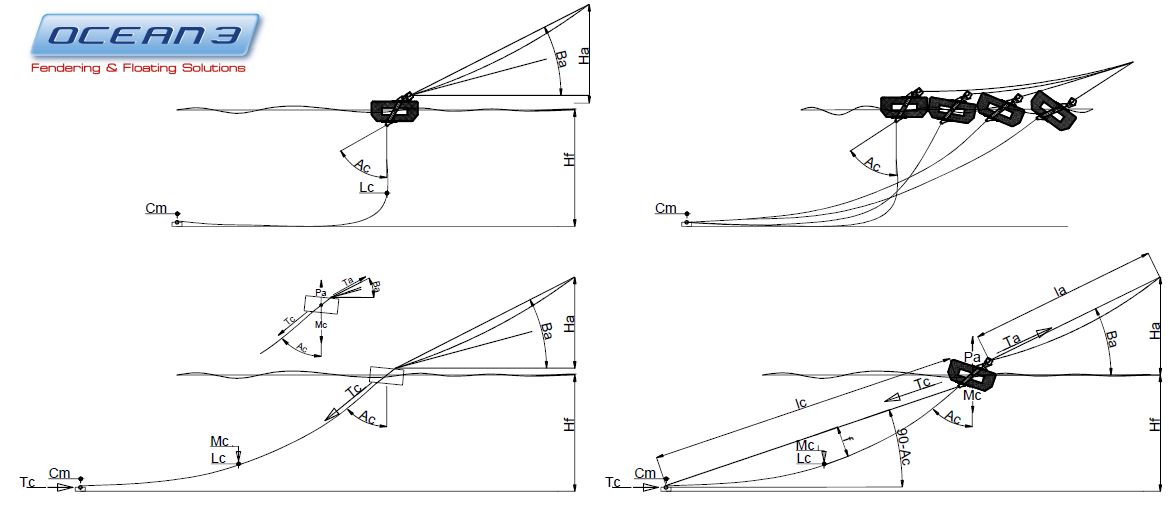
Calculation of the angle of the buoy with the mooring line.
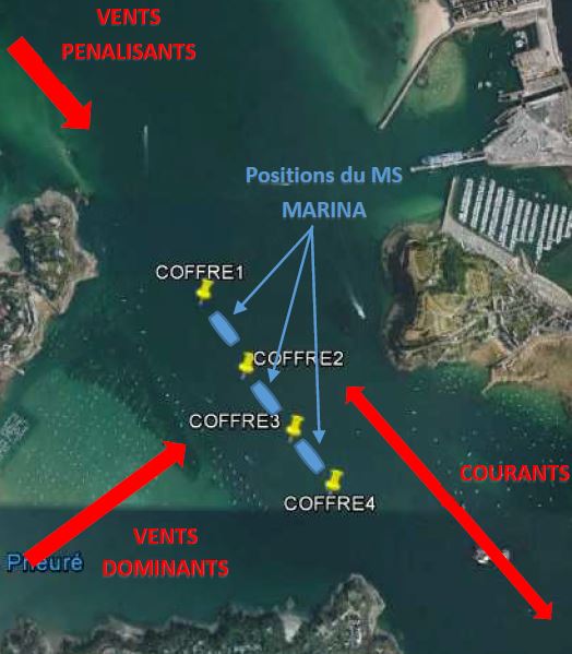
Calculation of the moorings with multiple anchor points.
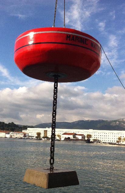
C) DRAFT AND FREEBOARD CALCULATION
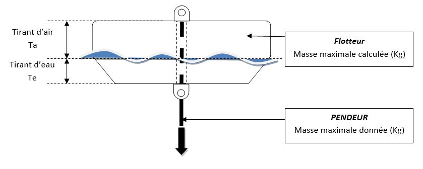
The buoy with the mooring line weight is represented above. The draft / free board will change depending on the weight of the mooring line.
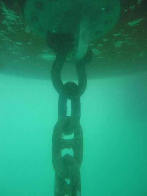
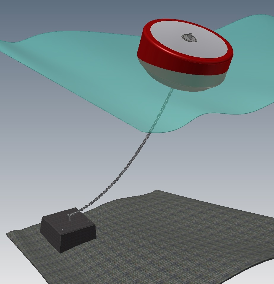
D) DEAD WEIGHT / SINKER
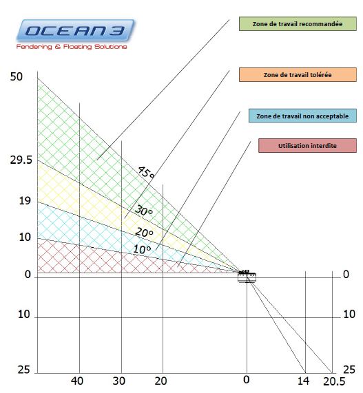
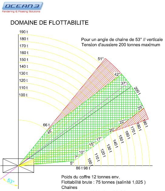
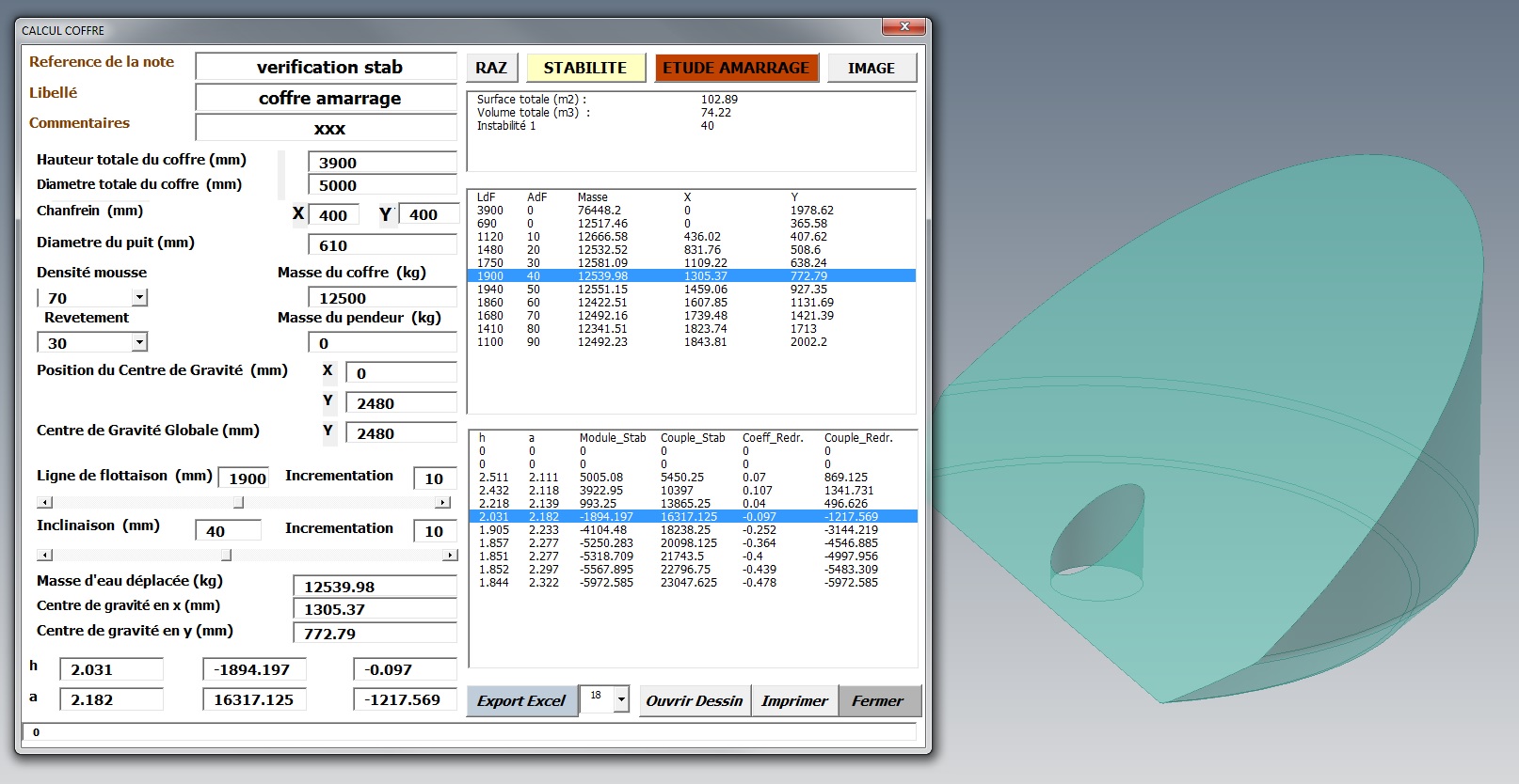
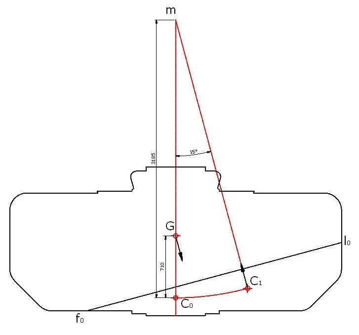
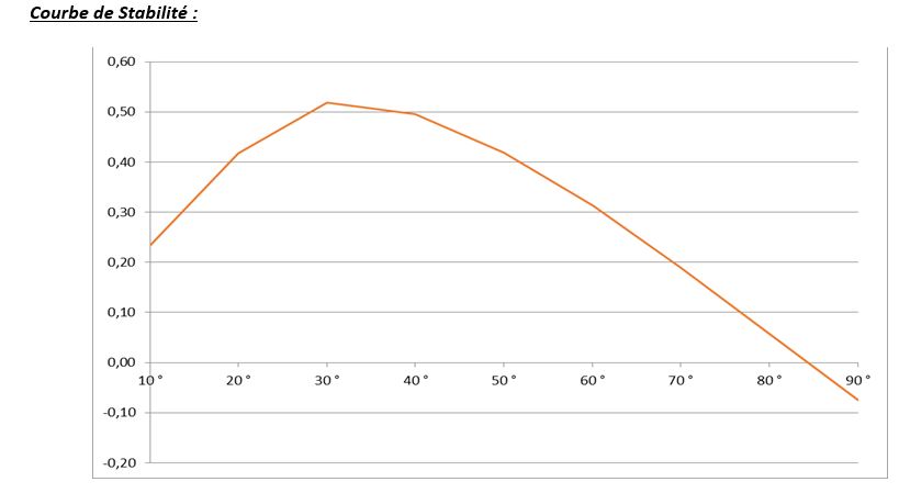
E) STABILITY CALCULATION
Having worked out the centre of gravity, we are able to represent the stability of the buoy when in full charge or without any moorings. All those figures have been calculated in 3d views.
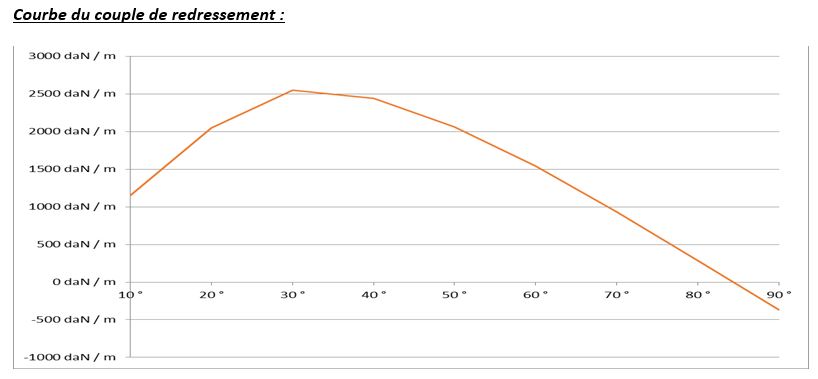
Stability simulation in full charge from 10° to 90° angle
Stability curves
III - DESIGN OF STEEL PARTS
A) STRAIN CALCULATION
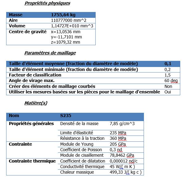
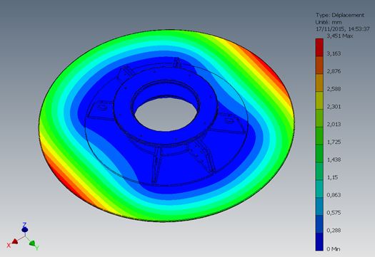
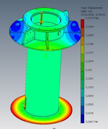
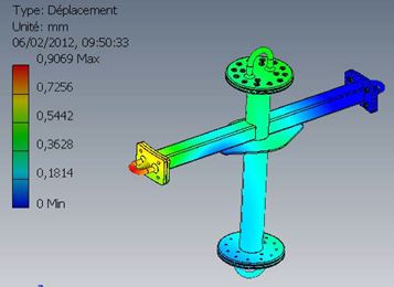
Strain Evaluations for the Steel Frames
B) DESIGN OF STEEL FRAMES
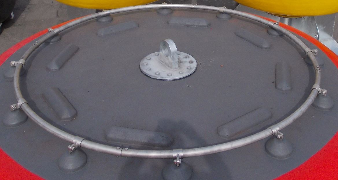
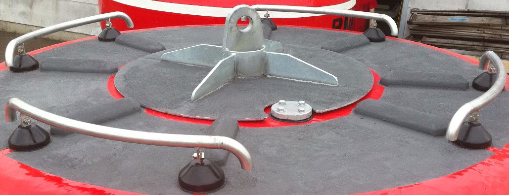
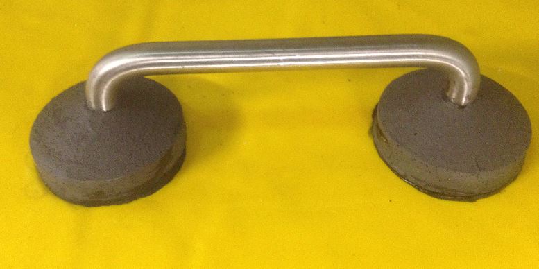
IV - ACCESSORIES
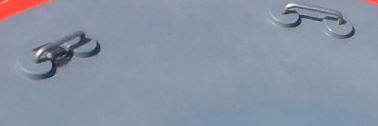
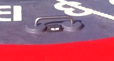
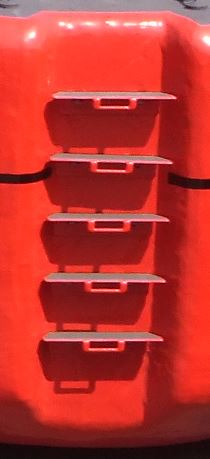
Foot rail continuous or in segments
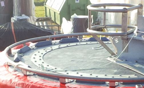
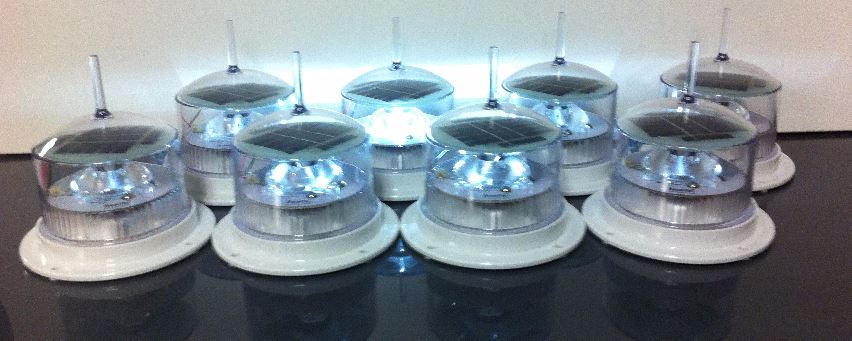
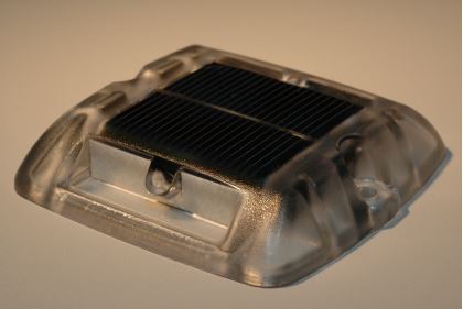
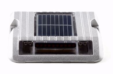
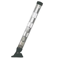
Hand rails and lights/lanterns
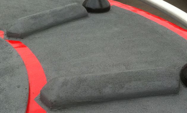
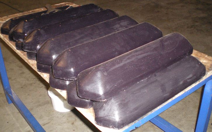
Decking steps

V - TESTS